PROJECT WINDRIGGER JUNE 2010 INSTALMENT
Back to Yacht Research Homepage | Previous page | Next page
ROUND-BOTTOM AND DORY HULL COMPARISON
During the last year I conducted performance trials of the Dory trimaran shown in Photo 1 and the round-bottom proa shown in Photo 1 & 6.
Using a GPS to measure speed, the proa attained a maximum speed of 6 knots whereas the Dory trimaran reached 8 knots - both propelled by my 3.3hp outboard motor.
The real difference in performance of these hulls was much more dramatic than indicated by the speed measurements - the round-bottom proa driven at maximum power, felt sluggish and showing that more horsepower would probably only dig a bigger hole in its wake.
Whereas the Dory felt lively and exhibited a potential to go faster with increased horse-power propulsion.
These results were contrary to my expectations because round-bottom hulls are claimed to be superior to hulls with chine-hulls because " they have lower-wetted surface".
But I found the wetted surface of the round-bottom proa hull, actually increases the hull moves through the water due to its waterline climbing above its static waterline - as shown in Photo 1.
On the other hand, the Dory hull reduces its wetted surface as its speeds through the water due firstly to its bottom surface directing water sideways with sufficient momentum to prevent it adhering to and flowing around its chine to its topsides.
It also further reduces its wetted surface as the forward 1000mm of its hull-bottom lifts out of the water resulting from its planing trim.
My 'discovery' was pre-empted by my mate Mike who produced the excerpt shown in Photo 3.
As an outcome of these trials my future multihulls will use chine planing hulls.
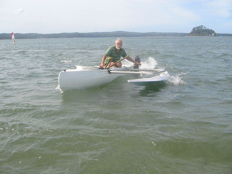
Photo 1 - The round-bottom proa I named Surfproa, driven by Mike Hadfield and powered by a 3.3 hp outboard motor.
This proa is 4700mm loa, 500mm hull-beam, outrigger hull 3600mm loa.
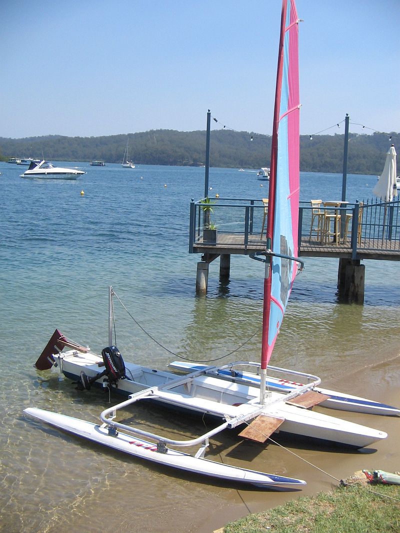
Photo 2 - The Dory-hull Planing Trimaran
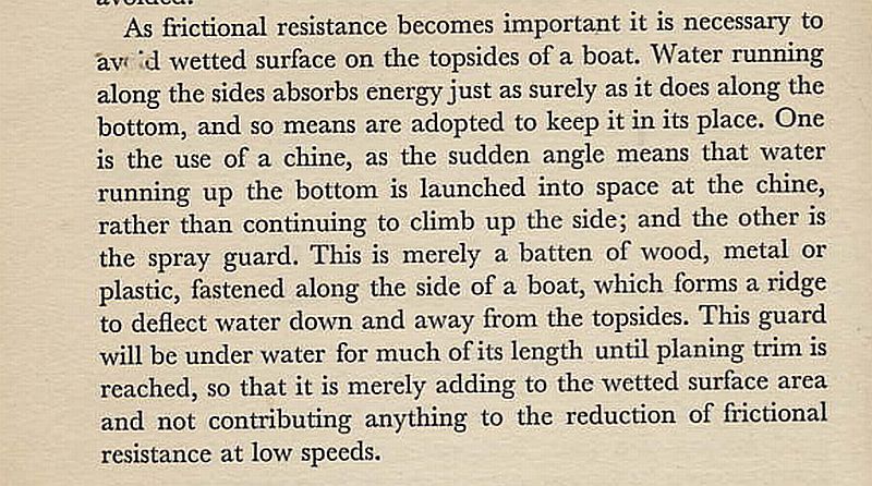
Photo 3 - Page 4 of the book by John Teale titled FAST BOATS published in 1961.
THE DORY PLANING HULL
Photo 4 shows the bottom my planing trimaran which is a truncated Dory that I designed to be the centrehull for the catamaran as shown in Photo 5.
This hullshape was derived from a symmetrical fore-and-aft Dory of 5400mm length along its bottom and was shortened (truncated) to provide a transon stern to support an outboard motor.
So its stern is located 1400mm aft of the midlength of a symmetrical Dory shape which is 2700mm from its bow.
Its bottom has rocker as shown in Photo 4 with a maximum fore-and-aft curvature is located at the maximum width of its bottom.
From my understanding of physics, it planes because at planing speeds its hull-bottom produces maximum hydrodynamic-lift due to a linear- momentum change of the water flow at the point of maximum curvature.
This allows the weight of crew and accommodation to be located around midships instead of aft as in most planing hulls.
This rocker appears to me to be an important factor for this Dory's ability to plane.
From this understanding I would expect a symmetrical Dory hull with its maximum rocker curvature located at its midlength, to produce maximum lift around midships - allowing it to used as a hull for a reversing/shunting proa.
I intend to substitute a Dory hull for the round-bottom hull of the shunting proa shown in Photo 12 of the October 2009 Instalment.
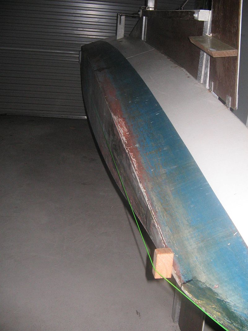
Photo 4 - THE PLANNING TRIMARAN HULL
Length of hull bottom 4100mm, maximum width 340mm located 2700mm from bow/bottom intersection lines.
Its rocker is defined by 35mm up at the bow and 20mm up at the stern measured from a horizontal line touching the hull-bottom its maximum width.
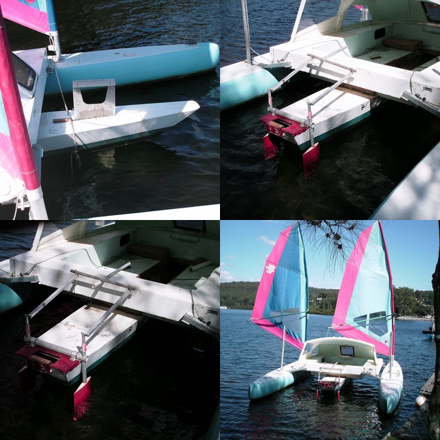
Photo 5 - Windriggercat 6800loa featuring the centrehull and side-mounted kickup rudders.
SURFPROA
During the last year I have developed the round-bottom hull ( described in the December 2006 Instalment), for use as a fishing and diving platform having the following capabilities: to safely negotiate surf ; to be carried on car roof-bars; easily transported across soft beach-sand; easy to paddle; resistant to capsize, unsinkable; comfortable and safe.
I have created it for towing behind my Transit van motorhome.
The outcome of this development is the proa shown in Photos1 & 6 -13 and which I have named Surfproa.
Its hull weight is 33 kg and the outrigger/crossbeam weighs 23 kg - so it is canbe carried on car-roofbars or a trailer, and transported across soft beach sand by one adult towing the beach carrier shown in Photo 7.
Two adults can carry it by hand.
The construction and shape of the Surfproa hull is shown in the December 2006 Instalment.
Its fibreglass end-sections are used as watertight lockers for stowing safety equipment.
Its round-hull surfaces, no keels and chines allow it to be pushed sideways by broaching waves without capsizing, and be much easier to steer through surf than most other watercraft.
The cockpit area has a floor which effectively provides a double-bottom and a third watertight space.
The proa shown in Photo 10 & 12 is designed as a shunting proa as for sailing with the outrigger to leeward.
Its sail area of 2.2sqm, is relatively small and was chosen to produce a speed up to its displacement-hull speed of 6 knots, and reduce the risk of capsize by sail force.
It is easy to paddle with a single-blade paddle using a J-stroke to paddle on one side and steering by sweep and draw strokes.
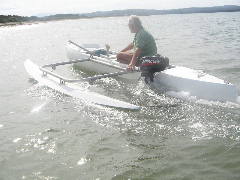
Photo 6 - Surfproa
I designed this outrigger with the aim to generate lateral resistance when used as an outrigger on a shunting proa.
It is clad with 4.5mm marine plywood and weighs 10 kgs.
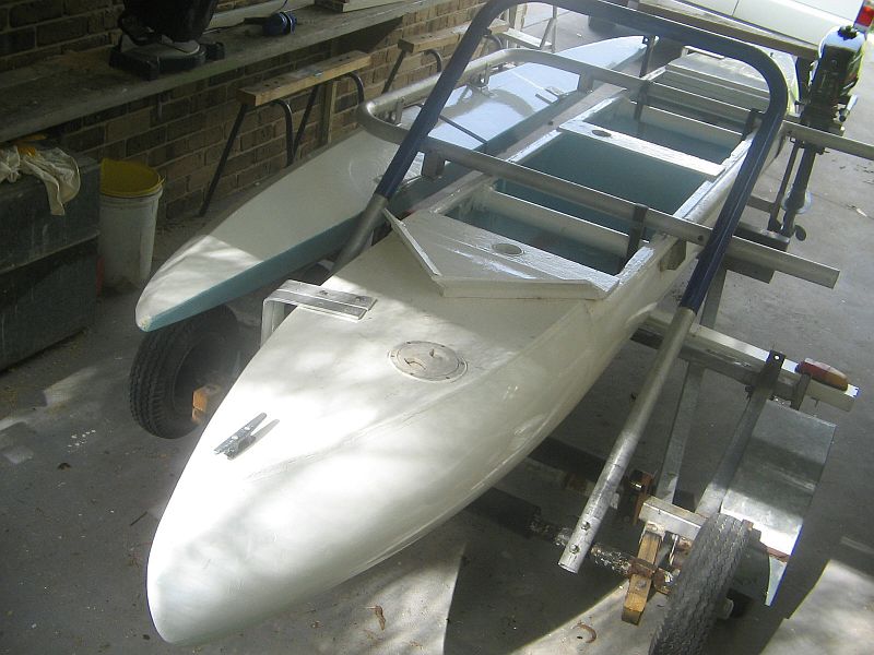
Photo 7 - Surfproa on a trailer - note the Beachcarrier axle and wheels stowed on the trailer
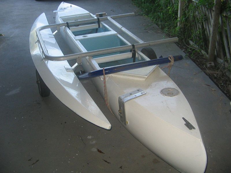
Photo 8 - The Surfproa on the Beachcarrier following unloading the carrier from the trailer, sliding the proa back onto it and rotating the blue carrier-draw bar over to rest on the proa-hull deck.
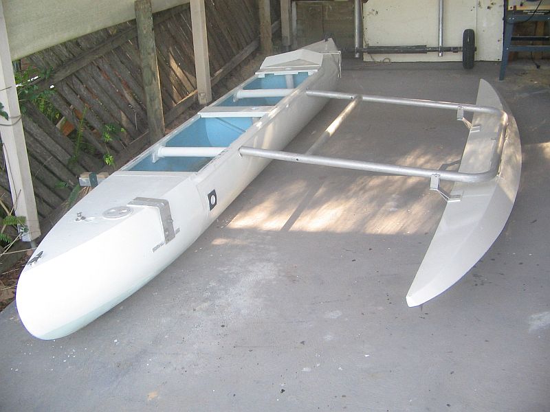
Photo 9 - Positioning the outrigger/crossbeam prior to attaching it to the Surfproa hull.
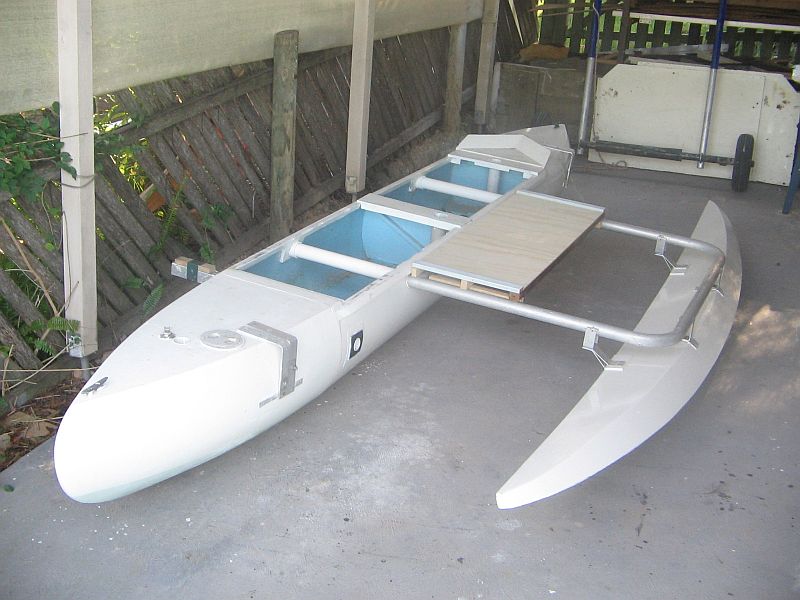
Photo 10 - Outrigger attached to the round-bottom hull.
Note the bridgedeck platform currently under development.
The gap bounded by the bridgedeck, crossbeams and outrigger hull, allows a swimmer/diver to get out of the water quick - an outcome of my close encounters with sharks during 20 years of spearfishing along the South Australian coast.
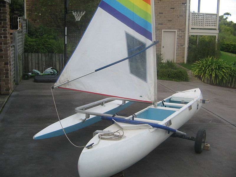
Photo 11 - Surfproa rigged as a shunting proa
Lateral resistance for sail/hull balance is planned to be generated by the outrigger, and steering by a paddle.
If this proves to be ineffective, two rudders as shown in photos 14 & 15 wll be installed and trialed.
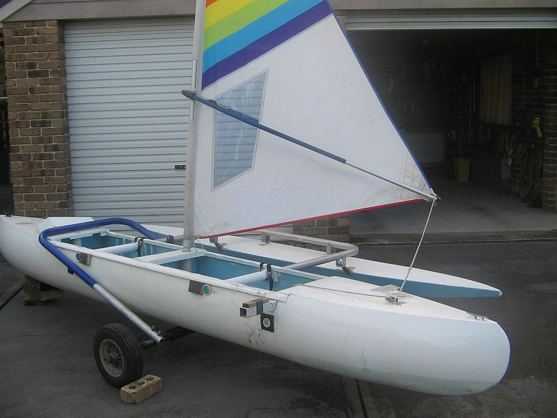
Photo 12 Surfproa as a shunting proa with its sail set for sailing in the opposite direction relative to that of Photo 11.
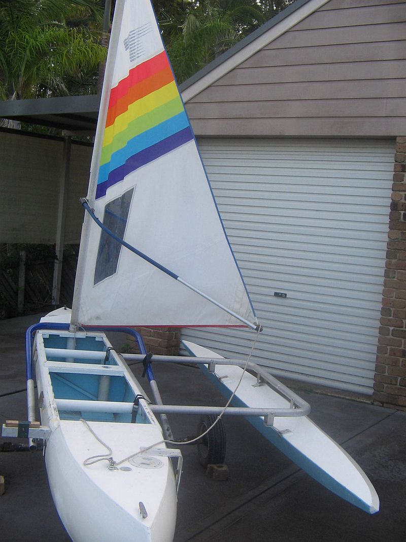
Photo 13 - Surfcat rigged as a tacking proa.
This sail can be used with or without the wishbone-boom and furled by rolling it around the mast.
Steering and hull/sail balance will be trialed using two side-mounted rudders such as shown in Photos 14 & 15.
Ultimately I aim to trial this rig with a trimaran configuration.
SIDE-MOUNTED RUDDERS
The rudders and centreboard/fins of my multihulls are designed for use including the shallow waters of lakes, rivers and seashores and I have expended a lot of time and effort on design and construction of them to cope with this environment leading ultimately to side-mounted rudders.
These have evolved from happenings such as my bottom-mounted spade rudders hooking onto mooring lines and a stern-mounted rudder which was destroyed when its associated boat was driven backwards by a sudden wind change into a river bank.
Also, I was impressed by an account witnessed by a mate, of the launching an off-the-beach catamaran which was stood on its stern by a wave - destroying its rudders and transoms.
The following photos show the outcomes of my experimental development of side-mounted rudders.
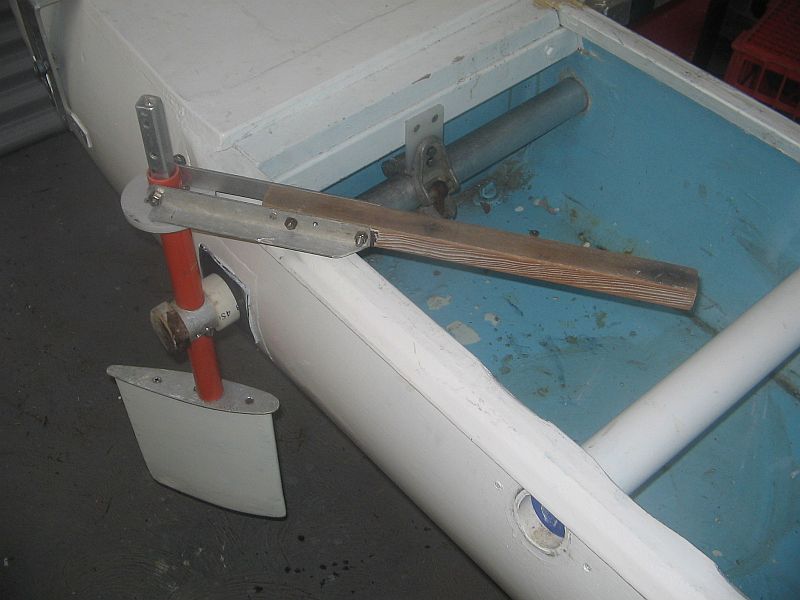
Photo 14 - My best rudder setup.
It is arranged to kickup fore and aft on grounding.
Kickup torque is adjusted by the scaffolding clamp attached to the 50mm dia. tube located across the inside of the hull.
The clamping screw is easily accessable to the helmsman.
The depth of the rudder can be changed by sliding the orange tube up or down followed by locking it to its supporting tube.
The rudder and tiller is reversable as requred for shunting a proa.
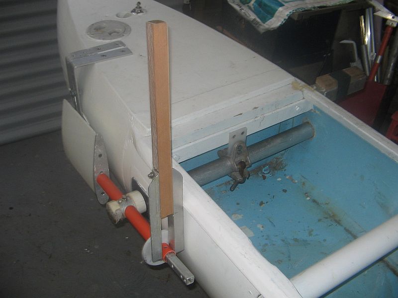
Photo 15 - The scaffolding clamp shown is used to adjust the kickup torque and lock the rudder in its up position.
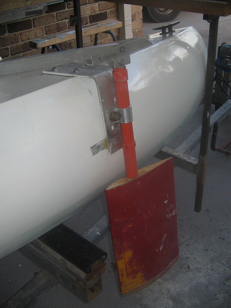
Photo 16 -Third-best rudder system - kick-up torque and rudder-depth adjusted by the bolt clamping the saddle around the orange tube.
This rudder reverses to a bow rudder on a reversing proa - the tiller is arranged to be lift over towards midships when the rudder is reversed.
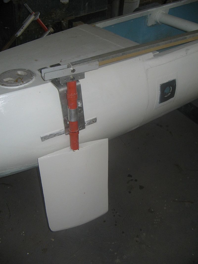
Photo 17 - Second-best rudder system
This fin has a symmetrical cross-section which when mounted on a proa, negates the need to rotate it 180 degrees following shunting.
It is a balanced rudder and consequently can flip side-on to the water flow if the helmsman looses hold of the tiller.
Also, it lack of the feel which provides feedback to the helmsman about boat speed and windward performance - which often leads to inexperienced helmsmen stalling these balanced rudders.
These problems can be prevented by installing fin-rotation restricting arrangrements - such as in this rudder arrangement where the fin is limited to 25 degrees rotation by contact with the hull topside.
This rudder fin is probably larger than required but it canbe easily changed to a smaller fin as all my rudder fins are constructed to slip onto a 20mm square tube as shown for example in Photos 18 and 19.
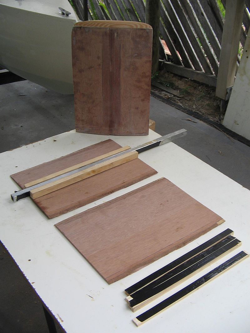
Photo 18 - Construction of the symmetrical rudder-fin.
Note the chamfered edges of the plywood sides of width to suit the contact angle of the fin sides.
The two timber spacing-pieces are spaced to provide a sliding fit on the 20mm square aluminium which serves as rudder-shaft.
The four black-tape timber-pieces are used to achieve an uniform glue-clamping pressure - the tape is attached to prevent the pieces becoming glued to the fin sides.
Epoxy varnish and glue was used on all timber fin-surfaces.
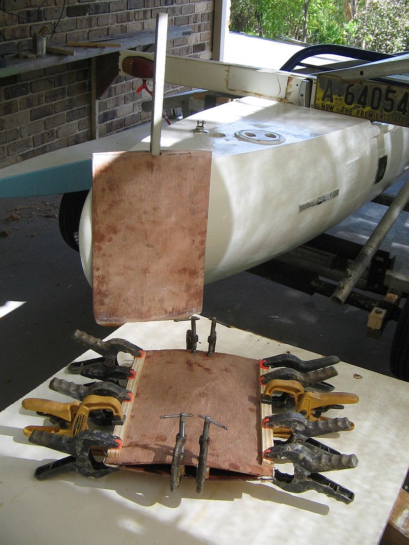
Photo 19 - Gluing the plywood sides of the symmetrical rudder-fin.
FUTURE DEVELOPMENTS
I intend to concentrate on trialing the Surfproa as a shunting and tacking proa ; and construct and trial it as a trimaran.
Of equal importance is sailing trials for the Planing trimaran.
I hope to complete plans for my plywood Dory-hull catamaran - 6200 loa.
Also design a new bridgedeck, centrehull and cabin for my 2 fibreglass 6800mm loa catamaran hulls.
Back to Yacht Research Homepage | Previous page | Next page
mailto:smithvanaalst@bigpond.com