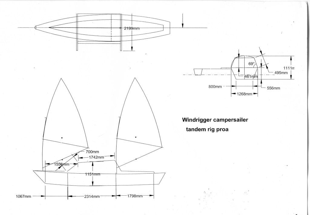
DRG 1. - Sketch of my campersailer - its 6200mm loa and most likely will finish up as a trimaran.
During the last year I designed and built a multihull to suit my requirements and fulfill the objectives of my project. I have named it Windrigger Campersailer - It is described by Drg. 1 and Photos 1-7. Launched it May 7.
Also I refurbished one of the hulls of my 6800mm loa catamaran and converted it into a proa and trimaran. It is designed for sailing and fishing along sea coast. I have named it SURFPROA 6800 and SURFTRI according to its configuration. I aim to trial it with the tamden sailrig shown in my June 1998 Instalment. Significant results from two off-shore sea trials using a single sailboard sail - the hull is very seaworthy and low-drag - it slips through the sea without disturbing it. During a 2 hour trial in choppy sea with 1 metre swells, the hull did not ship any water over its cockpit gunwale which were about 400mm above the sea surface. Niel, an ex-Abelone diver and multihull enthusiast provided motivation for developing of this multihull.
I built and trialed an outboard-leg fairing on my 3 hp. Mercury outboard, to reduce the turbulance created by its leg as shown in Photo 12. This fairing was devised by Gary Dierking - author of the book Building Outrigger Sailing Canoes.
Photos 13 -17 shows a novel leeboard system which I created and trialled - it is an outstanding success. I would appreciate answers and comments about these multihulls and problems listed below arising out of refurbishing the 6800 loa fibreglass hull.
DRG 1. - Sketch of my campersailer - its 6200mm loa and most likely will finish up as a trimaran.
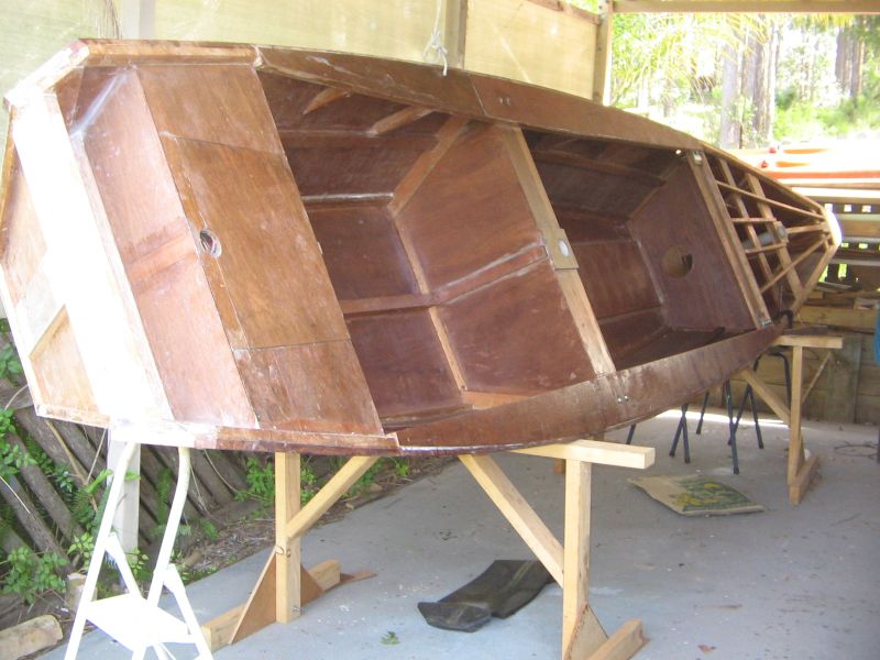
Photo 1 - Topside material 4.5mm ply skinned with 6 oz fibreglass cloth. Its flat bottom is 12mm ply painted on the bottom with epoxy flowcoat to reduce abrasion when sliding it over beach surface. The chines were screw-fastened, glued and fibreglassed.
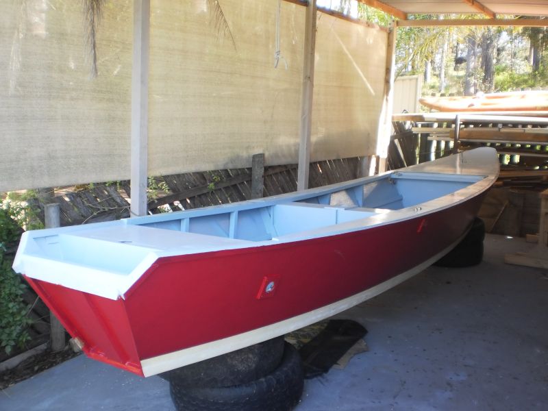
Photo 2. Transon for mounting long-shaft outboards. Portholes in the rear topsides for mounting a rudder one side and a 3 hp short-shaft outboard on the other side.
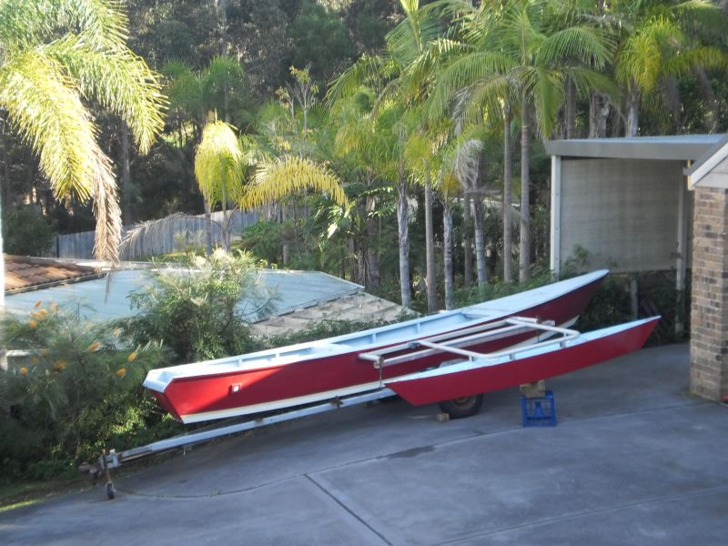
Photo 3 - Note crossbeams of 60mm dia. 3mm thick aluminium tube mounted through the hull just below the deck and fastened to the hull with U-bolts. It is rigged as a proa with the Dory outrigger - for its first trial.

Photo 4 - First launch, no wind. 5 knots speed with a Honda 2 hp outboard.
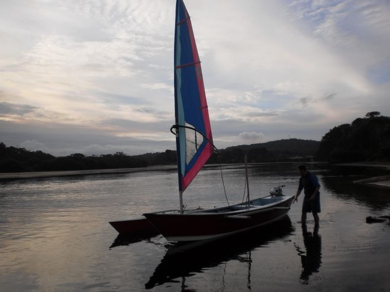
Photo 5 - We replaced the 2 hp.outboard with a 9.9 hp. which drove the boat at speeds estimated around 15 knots.
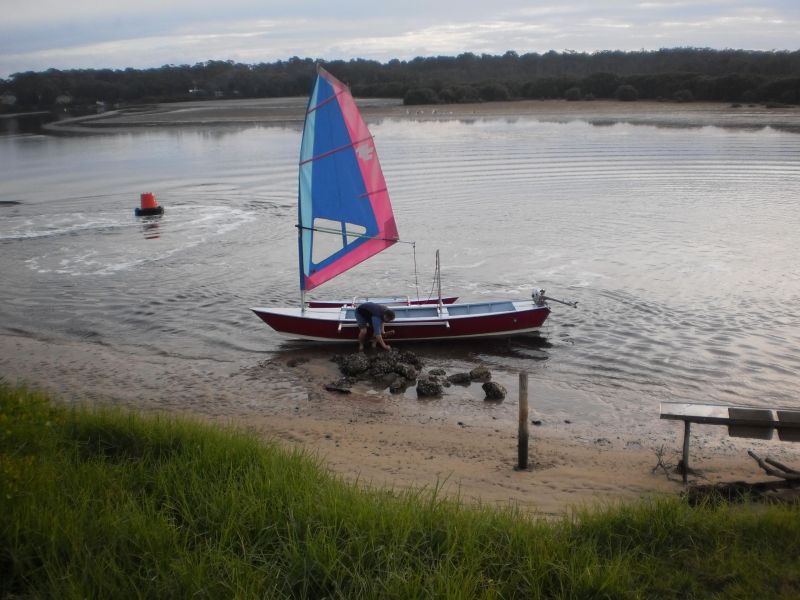
Photo 6 - Niel eating oysters on the Tomaga river at low tide about 1 Km in from the Tasman Ocean.
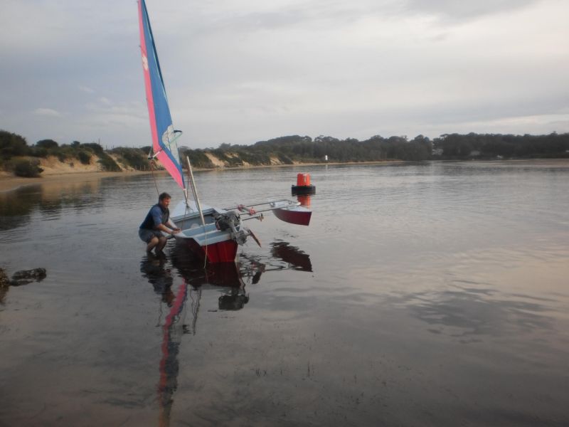
Photo 7 - !00Kg to lift the ama clear of the water.
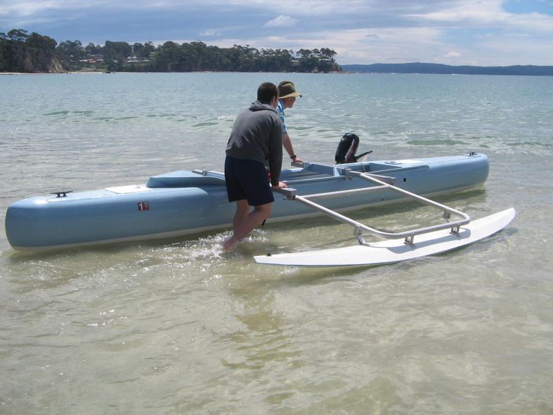
Photo 8 - First trialed SURFPROA 6800 as a proa powered by the 3 hp outboard.
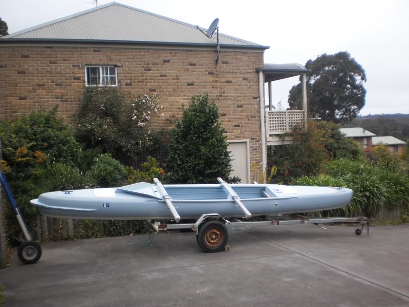
Photo 9 - SURFPROA 6800. Only real problem arising out of its first trial was the sea spray generated by the bow and directed at the crew. This lead to adding a spray deflecter shown in this photo which solved the spray problem.
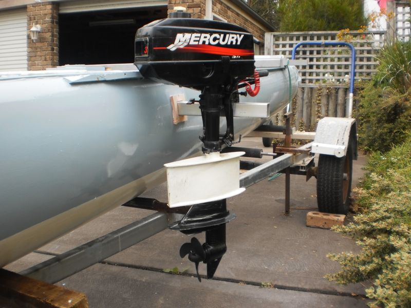
Photo 10 - The outboard-leg fairing devised by Gary Dierking. I built this fairing onto my 3hp outboard to reduce the turbulance created by its leg as shown in Photos 11 &12.

Photo 11- Note the outboard-leg fairing and the minimal turbulance at 8 knots speed compared to that of the unfaired leg shown in Photo 12
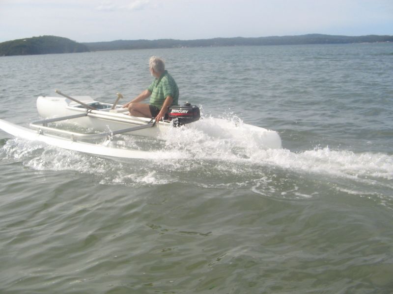
Photo 12 - Note the turbulance caused by the outboard leg without the fairing, powering the 4500 loa Surfproa.
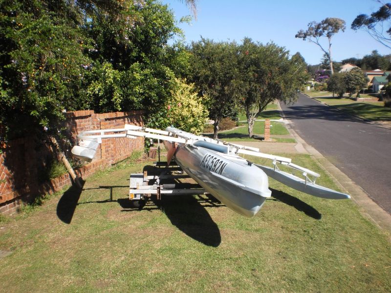
Photo 13 - SURFTRI 6800 - a trimaran using the half Crit 370 sailboard hulls as amas. Note the red leeboard mounted between the crossbeams and stowed in a kickup position
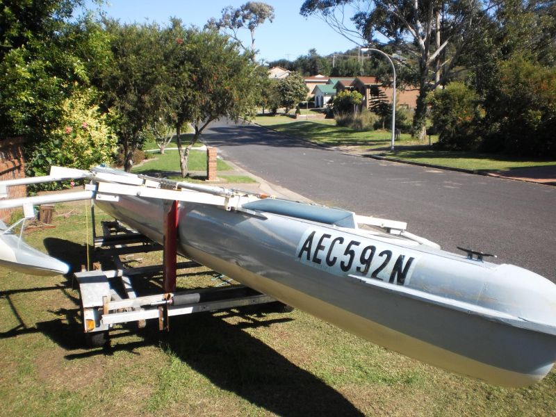
Photo 14 - The red leeboard set in the down position. When sailing to windward the leeward leeboard presses against the side of the hull by a hydrodynamic force produced by water flow across the leeboard which angled around 5 degrees to the hull fore and aft centreline. The windward leeboard moves away from its associated hull topside - and we lift it up as shown in photo 16 to reduce drag.
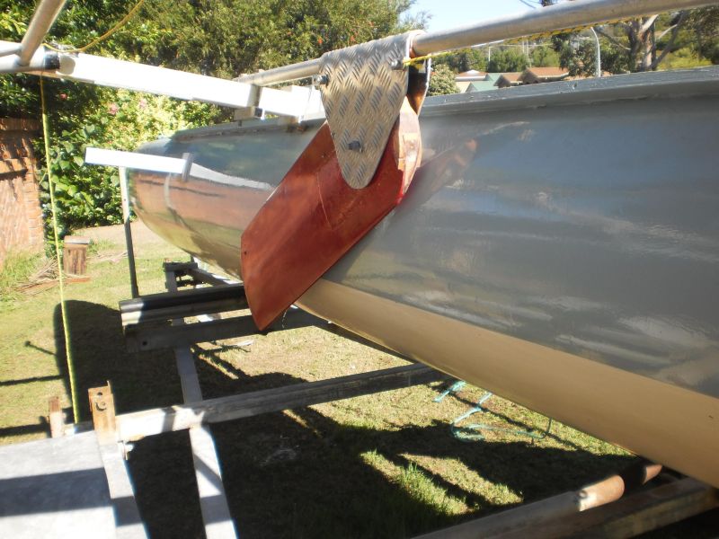
Photo 15 - The leeboard canbe positioned at any locations between the crossbeams. This allows the hydrodynamic force generated by the leeboard to be positioned near the line of action of the centre-of-effort of the sails and so reduce leeway and rudder drag. Also it allows the leeboard to be shifted to minimise leeway for different sailrigs and sail settings. Surprising how much lift this leeboard produces - during the trials with wind speeds rarely up to 5 knots it was difflicult to re-position the leeward leeboard because of the force it generated against the hull prevented it from being shifted by hand and the yellow rope system shown in photo 16 . Sailing in the light and varible winds, the leeboard pressure on the hull was a usefull indicator of wind direction - with both boards down, they move to indicate any wind changes.
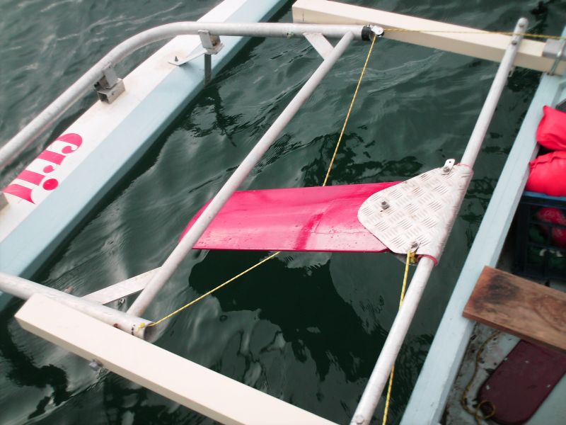
Photo 16 - Sailing to windward with the windward leeboard lifted up - it moves away from the side of the hull on tacking. Note that the 40mm dia. tube carrying the leeboard is set at angle of about 5 degrees to the fore-and-aft hull centreline so that it will develop the hydrodynamic force to oppose leeway. What I like about this system it possible to measure leeway forces using for instance a spring balance attached to the board and the bar of the ama frame.
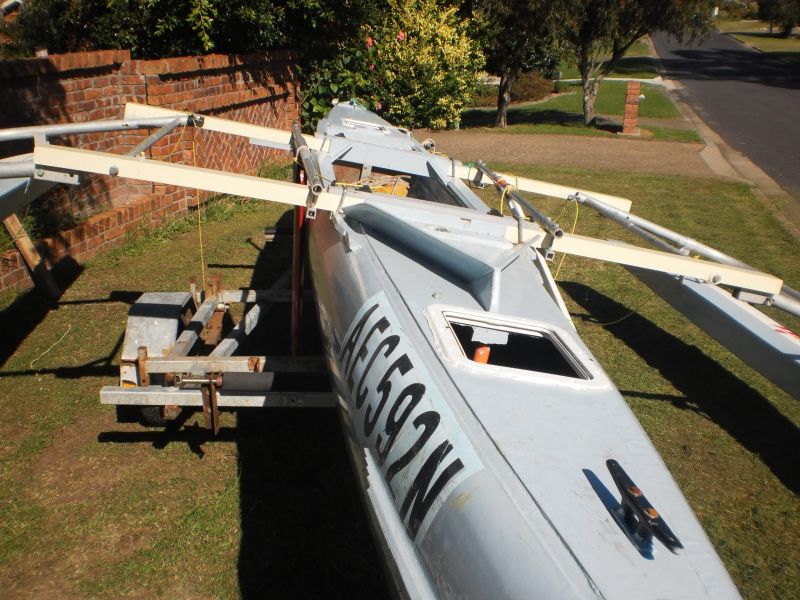
Photo 17 - Note the two leeboards - red one starboard side and white the port side. Maybe these leeboards can be used as lifting foils by shifting the two leeboard-supporting tubes outboard about 500mm.