PROJECT WINDRIGGER - OCTOBER 2009 INSTALMENT

Back to Yacht Research Homepage | Previous page | Next page

When I started this project I planned to design and build a trailer-sailer and go sailing it along the seashores of the Whitsunday Islands in Queensland on the East Coast of Australia. But I got side-tracked into investigating the physics of sailing to windward. I found much of this theory to be questionable and not supported by practice. The main outcome of this investigation is that the windward performance of my catamaran WRC6800 was greatly improved by locating its centreboard well forward of its sail centroid and installing it at an angle of 4-5 degrees to its fore-and-aft hull centreline to create a positive angle of attack. A description below covers my experimental results supporting this conclusion.

I class my beamchange systems as the best outcome of this project. It simply increases the beam of my catamarans from 2500mm to 3800mm and provides a tremendous improvement in sailing, comfort and safety. Details of it are included below and photos of my l beach-launching trailer.

HULL-SAIL BALANCE FOR WINDWARD PERFORMANCE

  1. My main task when trialling a new multihull is investigation of its windward performance. This involved determining the multihull's rudder/tiller rotation required to maintain its sailing direction. Acceptable windward performance is considered to be achieved with weather-helm - which is defined as the tendency of the boat to turn to windward and requiring the pulling the rudder- tiller to windward about 5-10 degrees rotation, to maintain its heading. Poor windward performance was defined by the boat tending to turn to leeward and requiring pushing the tiller to leeward to achieve a straight-line heading – named lee-helm. Most of my new multihulls initially suffered from lee-helm, which led me to studying the force diagrams covering the theory of sailing. These show the sailforce Centre of Effort (COE) and centreboard /keel fin Center of Lateral Resistance (CLR), aligned so that the centreboard/keel fin's hydrodynamic lift acts equal and opposite to the sailforce and consequently counters its tendency to push the associated hull sideways. The centreboard is shown angled to provide 4 - 5 degrees angle of attack - the optimum angle as shown on page 66 AYRS 41.

  2. In accordance with accepted practice, I had aligned the multihull's sail-centroid and centreboard CLR – but this did not produce weather helm.

  3. Searching literature on this subject, I found that this 4-5 degrees was not achieved in practice by trials conducted by Frank Bethwaite - see Photo 1 and a report by Edmond Bruce ref. AYRS 61 page 44. Their results showed angles of attack not exceeding 1.5 degrees - which would result in the centreboard producing negligible hydrodynamic lift and little contribution to the lateral resistance.

  4. I found a reference stating that the real COE of the sails is located forward of the geometric sail-centroid - so that the centreboard needs to be positioned forward of the geometric- centroid of the sails to achieve weather-helm.

  5. The lateral resistance produced by the rudder is not included in the force diagram – probably because the force diagrams were originated to cover deep-keel monohulls having rudders which were around 1/20 of the area of the deep-keel fin and therefore considered of negligible influence on the hull-sail balance. The larger multihull-rudders produce appreciable lateral resistance which combined with that of the centreboard, results in moving its CLR aft tending to increases lee-helm. Consequently the centerboard needs to be positioned further forward of the sailrig centroid to achieve weather-helm. So I shifted the centrecase and its 40mm thick centreboard forward of the bridgedeck on my 6800mm loa catamaran – but did not gain an improvement in windward performance.

  6. I then substituted a 6mm thick aluminiun centreboard which was free to rotate within the centrecase-slot effectively producing 4-6 degrees angle of attack. This resulted in a remarkable improvement in windward performance and ability to tack without manual assistance such as backwinding the sail.. This happening is published in my December 2004 Instalment. So I settled on this outcome - install the centrecase well forward of the COE and use a steerable centreboard such as shown in Photo 2.

  7. Another factor not included in the force diagrams is lateral resistance produced by the hull when sailing to windward. This hull-lateral resistance certainly contributed to windward performance of my Dory-hull multihulls as demonstrated by me walking along the Dory when under sail, from its stern to bow and seeing this boat's helmsman change from lee helm to weather helm. Also the bow-wave and spray produced by its lee-hull bow showed that this must be generating appreciable lateral resistance. This leads to the question - is this lateral resistance of sufficient magnitude to influence hull-sail balance and where is its line of action along the hull?. I never found an answer to these questions. To circumvent these unknown, I added vortex generators/bilge fences to the forward chines of the Dory hulls - described in July 2001 Instalment. Fortunately this factor was not a consideration with my round-hulled multihulls because they do not produce any noticeable lateral resistance.

  8. In the April 2008 Instalment I reported adequate windward performance using vortex-generators/bilge-fences attached to my round-hull 6800mm loa catamaran. Removing its centreplate during this trial showed that it was not producing noticeable lateral resistance. It also indicated that the catamaran was sailing to windward with an angle-of-attack much less than the 4.5 degrees shown on the force diagrams. Whilst its windward performance was proven adequate during a 5km sail to windward, it did not tack as easily compared to sailing with the tacking centreboard.

  9. My conclusion from the fore-going is that a catamaran with its centreplates installed along its fore-and-aft centreline, may not have adequate windward performance because its hull is not orientated to produce the optimum angle of attack of 4-5 degrees. Installing its centreplate 4-5 degrees to its fore and aft hull-centreline and angled to windward, should result in improved windward performance (if its hull has zero angle of attack).

  10. Apart from my trials, most of the theory and practice of windward sailing of catamarans is conjecture. The best way to start such an investigation is to measure the lateral force acting on the centreplate. Photo 3 shows how I intend to do this on my planing trimaran using a fishermen's balance. Another method - a load-cell sandwiched between the top of a centreplate and the adjacent centrecase-slot side would indicate the lateral force on the associated centreplate. Has such a measurement ever been performed.

Excerpt from HIGH PERFORMANCE SAILING by Frank Bethwaite:

Chapter Sixteen

The Quest for Speed

16.1 Forces on a sailboat when sailing to windward

If a perfect rig is mounted on a perfect hull, but one without a centreboard or keel, and it is sailed upright, it will not sail to windward. The 'wing in the air' (the rig) produces a force 'OS' (Fig 16.1), which is roughly at right angles to the sails.

The bottom of any planing hull is necessarily reasonably flat, and so in unable to produce much cross-boat force (unless it is heeled to put the chine deep in the water). As a result, in Fig 16.1, 'upright no keel nor centreboard' situation, the boat will accelerate in the direction 'OS' until the hull's drag increases to the point where it becomes equal and opposite to the sail force 'OS'. This situation, with the hull's centreline headed in the direction 'heading', but the boat tracking across the water in the very different direction 'OS', will neither win races, nor be much fun.

The best way to think about any sailing boat is to regard it as an assembly of three basic components:

  1. A wing in the air (the sails and rig)
  2. A wing in the water (the centreboard, or keel, plus the rudder)
  3. A form of low-drag flotation (the hull)
A force provided by the hull is primarily upwards, to keep the boat and crew from sinking. In the case of the very fast sailboards, the hull at rest is not big enough even to do this - it has to be moving fast enough to develop dynamic lift before it can support its rider. The hulls of most modern sailboats, except multihulls, are reasonably flat, and for this reason they can be usefully thought of as if they were saucer-shaped, i.e. free to move equally easily in all directions.

The keel or centreboard is a 'wing' which 'flies' through the water. Like the rig, it produces a force roughly at right angles to its surface 'OC', Fig 16.2 (b).

When a sailboat sails to windward or on a close reach, the forces acting on it when viewed from ahead, i.e. those forces which act across the boat, take the arrangement shown in Fig 16.2 (a). Appreciation of these forces is helpful in understanding which boats can and which cannot sail fast. For Fig 16.2 we will use figures typical of the many popular classes of non-trapeze conventional dinghies about 14 to 15 feet long which are of approximately similar performance and are well understood, such as the Gp14, Enterprise, Albacore, etc. These boats weigh about 350 pounds (300 for the hull and 50 for the rig and foils) and are designed to be crewed by two adults who will typically weigh about 310 pounds themselves and 330 pounds dressed for sailing and wet, so the total weight at which the boats are designed to sail is about 680 to 700 pounds. We will assume that the water is flat, that the True Wind is 12 knots, that the boat's heading when sailing to windward is 45 degrees from the direction of the True Wind, and that the boat speed through the water is 4.5 knots. The triangle of velocities in Fig 16.2(c) shows that the Apparent Wind becomes 15.5 knots, and blows at 12 degrees from the direction of the True Wind, and at an angle 'across the deck' of 33 degrees from the bow. These speeds and angles are reasonable, in that they are suggested by theory and confirmed by observation and measurement.

The leeway angle is different. Other authors have reported that they have found it hard to measure. We took one of our own designs - the marque shown in Fig 20.12 - which is designed to sail to windward in the design wind, with its centreboard running at an angle of attack of 3 degrees (i.e. with a leeway angle of 3 degrees), and towed a thread with a small weight at its end. While two of us sailed the boat, a third read the angle of the thread across the aft deck from the bow of a following motor-boat. It never showed anything like 3 degrees. It did not read even half a degree on any of a number of runs. We tried the direct observation approach. An observer stood on one shore of a narrow bay without tide and the crew sailed from near the shore on a fixed heading, which was about close-hauled, directly towards a conspicuous object on the other shore, The observer moved if necessary, until he was sighting along the boat's centreline at the aiming point on the far shore, and watched to see how much the boat drifted to leeward of the line of sight. It didn't drift to leeward either.

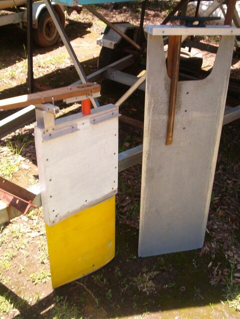
PHOTO 2 - Steerable yellow-centreboard and the self-tacking aluminium centreplate which was successfully trialled on WRC6800 during year 2003 - published in the Dec 2004 Instalment.

PHOTO 3 - Setup for measuring the lateral force on starboard leeboard of my planing trimaran

Joseph Norward,Jr "HIGH SPEED SAILING" page 58:
"The best steering, leeway resisting, and yaw stabilizing system for a proa is probably twin steerable leeboards near either end of the outrigger (leeward hull). The system would be very like that shown in Fig 5-10 except that the cases will be mounted with zero leeway angle and the bottom of the leeboards will consist of a spade rudder. The two rudders will work together driven by a wheel amidships as shown in Fig 5-11. As the major job of the shunting operation the rudders are turned around 180 degrees to put them in a balanced position and the bow board is raised somewhat with respect to the aft board. This can be done with tackle or, on a large proa, with hydraulics."

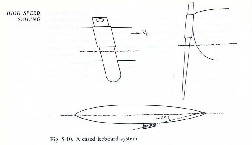
Photo 4 - Norwood's illustration.
This scheme is applicable to all multihulls.

BEAM-CHANGE AND BOAT TRAILERS

Photo 5 shows the beamchange system I developed for my Dory-hulled catamaran, using rollers in contact with the catamaran's topsides supporting it on the trailer. I tried to use this trailer for carry my round-hulled fibreglass catamaran and found that the rollers produced a serious indent in the hull surface - requiring adding reinforcing stringers inside the hull opposite the roller track. This problem was resolved by supporting the catamaran on trailer-rails in contact with the underside of its bridgedeck - as shown in Photo 6-8.

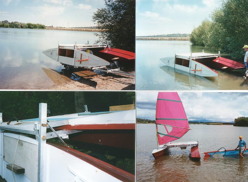
PHOTO 5 - Beamchange system for WRC 5600

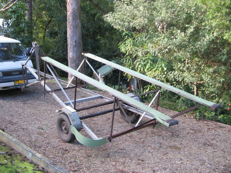
Photo 6 - Trailer for WRC 6800 catamaran, trailering beam 2500mm, sailing beam 3800mm.

Note the trailer-tilting mechanism at its tow-ball end, which enabled launching and reloading to be performed without submerging its wheel bearings and Independant Rubber Suspension system - to reduce seawater corrosion. The green plastics-strips spanning the trailer end-corners and mudguards were added to prevent the cataramaran's bows tucking under the bottom of the mudguards during reloading.

Photo 7 - Launching WRC 6800..

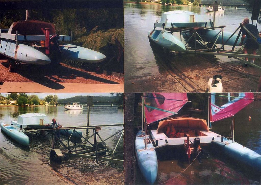
Photo 8 - Reloading WRC 6800.

Launching and reloading requires no more than 10 minutes and can be performed by one person. The beamchange system is automatic and fail-safe from the point of view that the catamaran's crossarms are held against brackets on its bridgedeck by the water-upthrust on its hulls - four 12mm bolts are used to clamp these joints for safety sake.

BEACH-LAUNCHING TRAILERS

Launching and reloading boats at launching ramps requires considerable skill and judgement, particularly when reversing an empty boat trailer onto and down the ramp obscured by the bulk of my Transit van. Add to this further threats such as a drop-off at the end of the ramp at low tide, tidal current and soft-sand. So following moving home closer to our sea coast, I become interested in launching multihulls from beaches as shown in the photos 10 - 11.

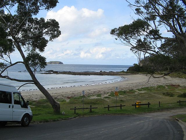
Photo 9 - Wimbie Beach I km from my home - note the gap in the fence.

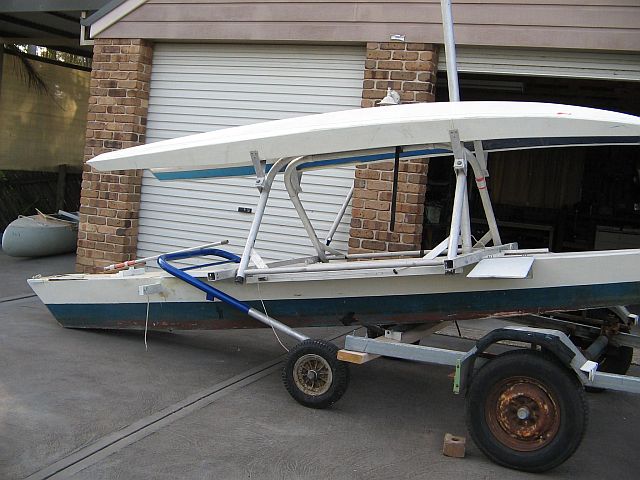
Photo 10 - Loading my planing trimaran onto the beach-trolley (the wheel/axle/Ubar) from its road trailer.

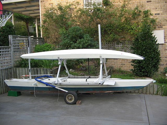
PHOTO 11 - Trimaran loaded onto the beach trolley.

My plan is to carry the trimaran to Wimbie Beach on its road trailer and off-load it onto the beach-trolley and manually wheel it through the gap in the fence to the sea.

PHOTO 12 - My latest creation - Atlantic proa using fore-and-aft rudders for steering and lateral resistance.

Back to Yacht Research Homepage | Previous page | Next page


mailto:smithvanaalst@bigpond.com