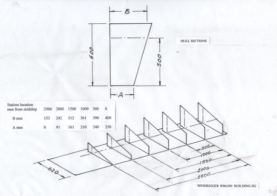
Drawing A - Windrigger WR 6200 Building Jig drawing
During our last Winter I developed a simple and quick way to construct the plywood hull of an extended version of Windrigger MK I (WR6200) which maybe for construction of a catamaran, proa or trimaran . My objective is to provide plans and building instructions that would appeal to those who have no prior boat-building experience. The plans shall comprise many photographs instead of detailed drawings, all contained in a CD-ROM.
Another objective is to provide a way for amateur yacht researchers to tryout their ideas without first having to learn about boatbuilding required to build a platform for their experiments - as I have had to. This method allows them to vary the main dimensions of a hull to suit their requirements.
The boatbuilding method comprises first building the sides of the hull, using a building jig to position its components and set the designed curvature of the sides. Two sides of the hull are then placed together, temporarily fastened at bow and stern and spread apart by inserting two bulkheads, followed by adding cross-framing. Finally, top and bottom panels are fastened to the chines and sheer clamps.
The following covers a description of this boatbuilding method and a half-length hull I constructed to illustrate the method and prove my ideas and calculations. This hull was made from cheap non-water-proof materials to facilitate tryout of various boatbuilding techniques, framing schemes and aesthetic features of the hull. I labelled it - the Tryout hull.
WR6200 is nominally 6200mm loa with a Dory-shape hull of midship cross-section of 500mm across its bottom, 800mm across the deck, and 500mm deep and symmetrical fore and aft. I used mathematics to define the hull shape and particularly the surface shape of its side which is part of a cone. I calculated a set of coordinates defining this conical surface and used them to realise this surface on the building jig shown in Drawing A.
Drawing A - Windrigger WR 6200 Building Jig drawing
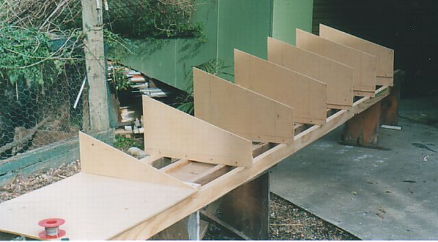
Photo 1 - Wrg 6200 Building Jig.
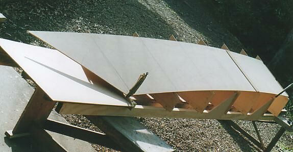
Photo 2 - marking the chine and sheer-line intersection points on the jig sections. (The transverse strap shown on the hull surface covers a but-joint instead on a scarf-joint which would be used for a real hull)
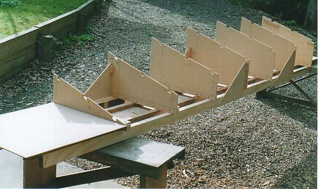
Photo 3 - cut-outs for the chine, sheer and stiffener stringer.
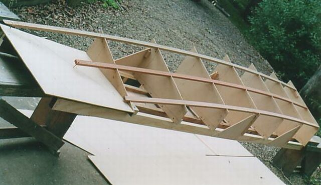
Photo 4 - chines, sheer clamp and stringer positioned on the jig.
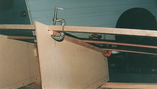
Photo 5 - Cross-section logs are glued to the chine,sheer clamp and stringer.
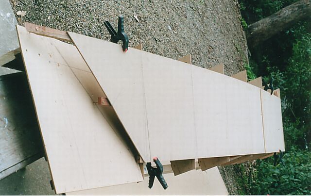
Photo 6 - The side panel is glued to the chine, sheer clamp and stringer.
To assemble the half-length hull, the two sides were attached at the bow, a bulkhead was inserted and fixed in position to spread the sides apart, and bottom and deck transverse timbers were clamped to their corresponding cross-section logs as shown on Photo 7.
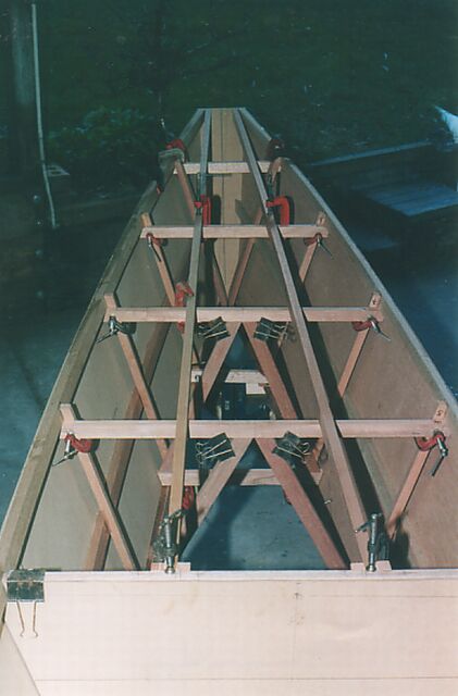
Photo 7 - Side panels spread apart by a bulkhead and cross-section framing installed.
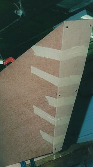
Photo 8 - Bow section taped to the sides of the hull at bow.
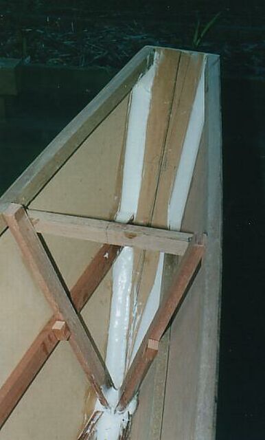
Photo 9 - Bow section glued to the hull with epoxy filleting compound.
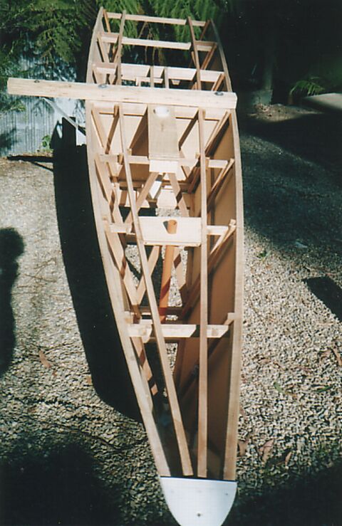
Photo 10 - top view showing stubmast support and rudder post.
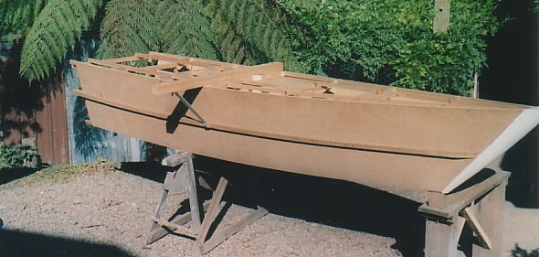
Photo 11 - Featuring the catamaran beam-change arm and bow-block.
Another example - this jig may be used to produce a proa or trimaran hulls of the following dimensions:
Hull similar to WR 6200 but with hull height reduced to 400mm resulting in a loa of 5800mm, 400Kg displacement at 212mm draft.
Outrigger-hull midship cross-section 250mm bottom, 450mm deck, height 300mm and 4144loa.
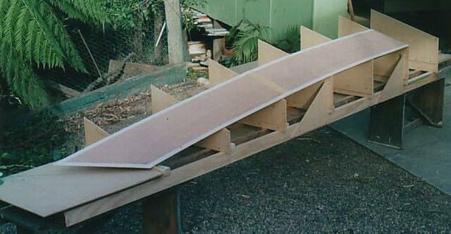
Photo 12 - Building jig used to produce hull sizes other than WR62000.
The sheer line and rocker are the result of the parallel fore-and-aft edges of the side panels - producing an 80mm rise at the bow. Parallel was selected to simplify cutting out the side panels and fortunately it looks o.k. To obtain a particular rocker and or sheer line, the associated vertical offsets are marked out on the jig cross-sections and transferred to its associated side panel.
The best way to produce the side panel is to first cut the side panel from 3mm fibreboard use it checkout the aesthetics, shear line and rocker, and ultimately use it as a template to mark out the much more expensive marine plywood side panel.
The description is based on a half-length hull jig which was used solely to facilitate tryout and development of the building method. In practice a full-length jig would be used to build the two sides of a hull.
The hulls described above are symmetrical fore-and-aft. This form was selected as it minimises jig construction, provides constant chine and sheer log angle (16.7 degrees) allowing them to be machined before installation, and provides constant form-stiffness for the plywood side-panels. The method may be used to construct hulls that are not symmetrical fore-and-aft.
There are many variations of the building method - for example an asymmetric hull maybe produced by using two jigs of different fore-and -aft curvature.
The WR6200 hull is 500mm longer than Windrigger MK I. This was done to increase its fore-and-stiffness and increase its ability to carry sail in high winds.
There is sufficient information in the fore-going and in the other pages of Project Windrigger on this website, for a persion wlth some knowledge of boatbuilding, to build WR6200 or variations of it. I welcome your questions and comments
February 28 - a successful trial of a tacking centreplate which comprised an aluminium plate 8mm thick, 355mm wide and in- water-depth of 500mm, free to move in the centrecase slot to provide 7 degrees angle of attack and designed to automatically move to a positive angle of attack following tacking. The cat tacked perfectly - no need to backwind a sail or paddle around as required on the earlier trial.
March 25 - wind strength 5knots, laborously tacked out to sea against the tide, from the other side of bridge shown in the photo. The cat showed no problem in riding the confused sea-chop around the breakwater and swell out to sea - no impacts on the underside of the bridgedeck which is not more than 300mm above still-water surface.
